
Vibration analyses
There are production lines in which vibrations are generated on purpose. They may employ a vibrating machine to fluidize some bulk freight, for instance in a drying process, or a machine to shake a mixing vessel. Apart from these special cases, vibrations usually are unwanted, and mostly the appearance of vibrations is associated with upcoming trouble. Indeed the occurrence of unexpected vibrations should not be treated lightly. The point is that a vibrating structure is never moving uniformly. Vibration always implies deformation of that structure and with it internal stresses – oscillating internal stresses. Alternating stresses can cause fatigue failure at stress levels far below the yield strength of the material. Thus a structure exposed to vibrations over a longer period of time runs the risk of being damaged in the long term. Structural steel work can break, in particular at welded joints. Vibrations acting on rotating machinery can cause premature wear of the bearings.
- What causes vibrations to occur in our machine or our construction?
- Is the vibration level critical or is it tolerable?
- Which design configurations or process parameters do have an impact on the vibrations?
- What can we do to avoid vibrations or at least decrease vibration intensity?
These are some of the questions which will be answered by a vibration analysis.
Physics in Industry offers support in clarifying and solving your vibration problems and questions concerning vibrations. There are several tools which we will employ, depending on your particular plant design and your special demand. These are:
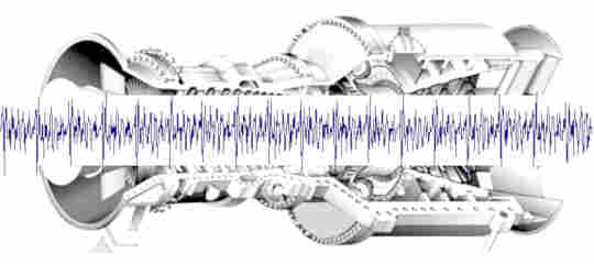
Vibration measurement
Why measure vibrations? There are some good reasons for it:
- To find out the cause(s) of vibrations.
- If the causes are already known: To investigate the amplitudes and to assess its potential for damage.
- To inspect or monitor rotating machines.
If vibrations appear totally unexpectedly, the first step must be to find out the cause of it. By means of vibration measurements it's easy to determine vibration frequencies, vibration amplitudes and vibration modes, and to investigate how this quantities depend on variable production parameters. These results help to identify the driving force.
By means of vibration measurements we will determine oscillation amplitudes in structures and machines. In a harmonic analysis we then calculate the resulting stress amplitudes and in a subsequent fatigue analysis we will assess its potential for damage.
Recording the primary measuring signal of a sensor provides its acceleration-time-history. Fourier transformation (FFT) of these data over a short time period results in the frequency spectrum valid for this time period. Combining the frequency spectra of subsequent time periods in one diagram visualizes the temporal development of the frequency spectrum (waterfall diagram).
Another field of application is the diagnosis and monitoring of rotating machines such as motors, gears and turbo engines. Highly sensitive accelerometers, attached to the outside of the machine housing, will detect even the smallest deviations from a uniform running, may be, due to some slight imbalance at the rotor, or may be due to tooth wear or a broken tooth in the case of a gearbox or some other defect. In a rotating machine, a defect like this means a periodically acting force on the rotor and, as a consequence, on the machine housing, which translates into some extra peaks in the frequency spectrum. Bearing wear, in contrast, paints a totally different picture: The frequency spectrum then appears rather chaotic.
Modal analysis
The purpose of a modal analysis is to determine the normal modes of oscillation und the corresponding eigenfrequencies of structures and components. This is done by means of a finite element analysis (FEA). Best practice is to do this analysis in an early engineering stage, for example as part of the detailed engineering. In this way, expectable eigenfrequencies of a structure are known in advance, and vibration problems caused by resonance can be avoided. If you're planning, for example, a framework for a vibration conveyor, who's oscillation frequency is adjustable within a certain range, you have to make sure that none of the eigenfreqencies of the framework will lie in that range. Otherwise vibration problems will almost be predetermined.
Stiffening an existing structure is a customary way to shift an eigenfrequency upwards, out of a critical range. Of course you should be aware of the eigenfrequencies of the existing structure as well as of those expected in the modified structure to not run even more into trouble.
Harmonic analysis
The purpose of a harmonic analysis is to determine, how a structure will behave, if it is exposed to an oscillating force at a certain frequency. For example, an oscillating conveyer or a vibrating chute for some bulk material may be driven by an unbalance motor. The motor is exerting a sinusoidally oscillating force on the conveyer which will make the latter oscillate at the same frequency, however, with a phase shift and an amplitude depending on the position within the conveyer. As a result, the conveyer will experience an oscillating deformation accompanied by internal stresses. The stress amplitudes will depend on the construction design of the conveyer, on the materials, and, of course, on the amplitude and the frequency of the driving force. In this case, the conveyer will not oscillate at one of its natural frequencies (which may be investigated in a modal analysis), but at the frequency forced by the motor. If the conveyer is designed correctly, the exciting frequency will not match any of the conveyer's natural frequencies. (Otherwise, the resulting deformations and the internal stress levels would be very high and the device's lifetime probably very short.) The smaller the gap between the exciting frequency and any of the natural frequencies, the higher the resulting stress amplitudes and the shorter will be the lifetime of the device.
In a harmonic analysis a finite element model of the construction to be investigated is created, and the exciting forces are included through appropriate boundary conditions.
Ultimate target of the analysis and main interest of the design engineer is to know the vibration-induced stresses and, especially, stress amplitudes and mean stresses at the hotspots. The locations of these hotspots typically turn out not to be in places of maximium displacement, but, quite contrary, in positions which are rather constrained.
If the exciting frequency is variable it makes sense to do the analysis for several frequencies. Once the finite element model is created, it just needs to change the boundary conditions for each frequency and start another computational run. In this way, the dependency of the internal stress amplitudes on the excitation frequency can be monitored. This procedure is called a frequency response analysis.